
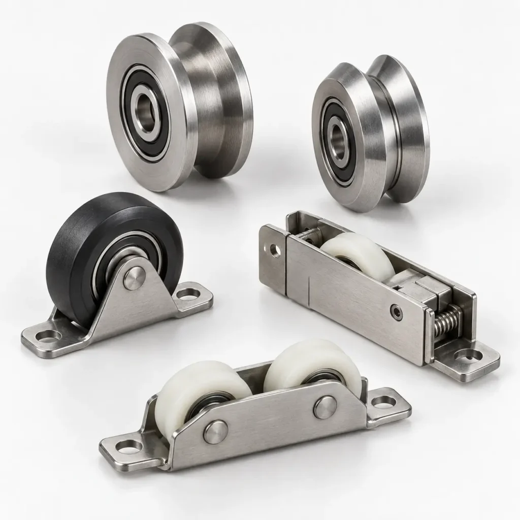
A non-standard bearing for a door or window system is rarely identified reliably from one photo or a stamped bearing code. The bearing may be hidden inside a pulley, plastic wheel, metal housing, bracket or complete roller assembly. For B2B replacement and OEM programs, the safest route is to convert the existing sample and installation data into an approved, measurable drawing.
Why Door and Window Bearings Become Non-Standard
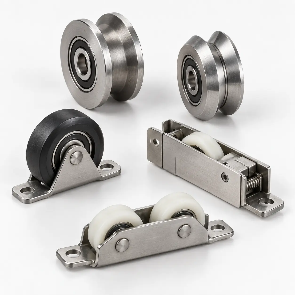
Architectural hardware often stays in service for many years, while the original roller supplier, extrusion system or component reference disappears. A replacement may need a special bore, outer diameter, extended ring, flange, sleeve or a bearing integrated into a dedicated wheel. Regional aluminium profiles and private-label hardware systems also create dimensions that do not match a current catalogue part.
Our non-standard deep groove bearings for door and window systems page covers the bearing-focused route. If the requirement is a complete polymer or metal wheel, also read the existing guide to custom bearing wheels for sliding doors and windows. These are related but not identical product specifications.
First Define the Quotation Boundary
| Product level | What must be measured | Typical buyer wording |
|---|---|---|
| Bare bearing | Bore, bearing OD, ring width, closure and ring features | Special-size bearing, extended inner ring bearing |
| Finished wheel or pulley | Bearing core plus finished OD, width, groove, material and hub | Window roller bearing, U-groove pulley, nylon bearing wheel |
| Complete assembly | Wheel plus axle, bracket, adjustment and mounting interfaces | Sliding door roller, window pulley assembly |
If the quotation boundary is unclear, two suppliers may quote completely different products under the same description. Photograph the part before disassembly and show which components must be supplied.
Photograph the Sample Before Measuring
- Take front, side, rear and angled views against a plain background.
- Include a ruler or caliper reading in at least one image for scale.
- Photograph the part in the installed position and the empty mounting location.
- Record every bearing mark, moulded number, logo and left/right designation.
- Show the rail or track cross-section where the roller makes contact.
- Photograph wear, cracks, corrosion or deformation separately.
Do not rely on the sample name used by a local installer. Terms such as “aluminium window wheel,” “sliding door bearing” and “pulley roller” cover many incompatible geometries.
Measure the Bearing Core Separately
When disassembly is possible, record the bore (d), bearing outside diameter (D) and bearing width (B). Note metal shields, rubber seals or open sides, and photograph any extended inner ring, flange, groove or sleeve. A stamped 608, 625 or 626 reference may identify a standard core, but it does not define the surrounding wheel or bracket.
For model and closure comparisons, use our 608ZZ, 625ZZ and 626ZZ selection guide. For a compact custom size, see special-dimension miniature deep groove bearings.
Measure the Finished Roller and Track
Record finished outside diameter, complete width, groove width, groove depth, groove radius or V-angle, flange diameter, hub length and the location of each shoulder. If the roller runs on an aluminium or steel rail, include the rail width, height, radius and contact location. Our grooved roller bearing specification guide shows why the track section is as important as the wheel diameter.
Correct for Wear Before Freezing the Drawing
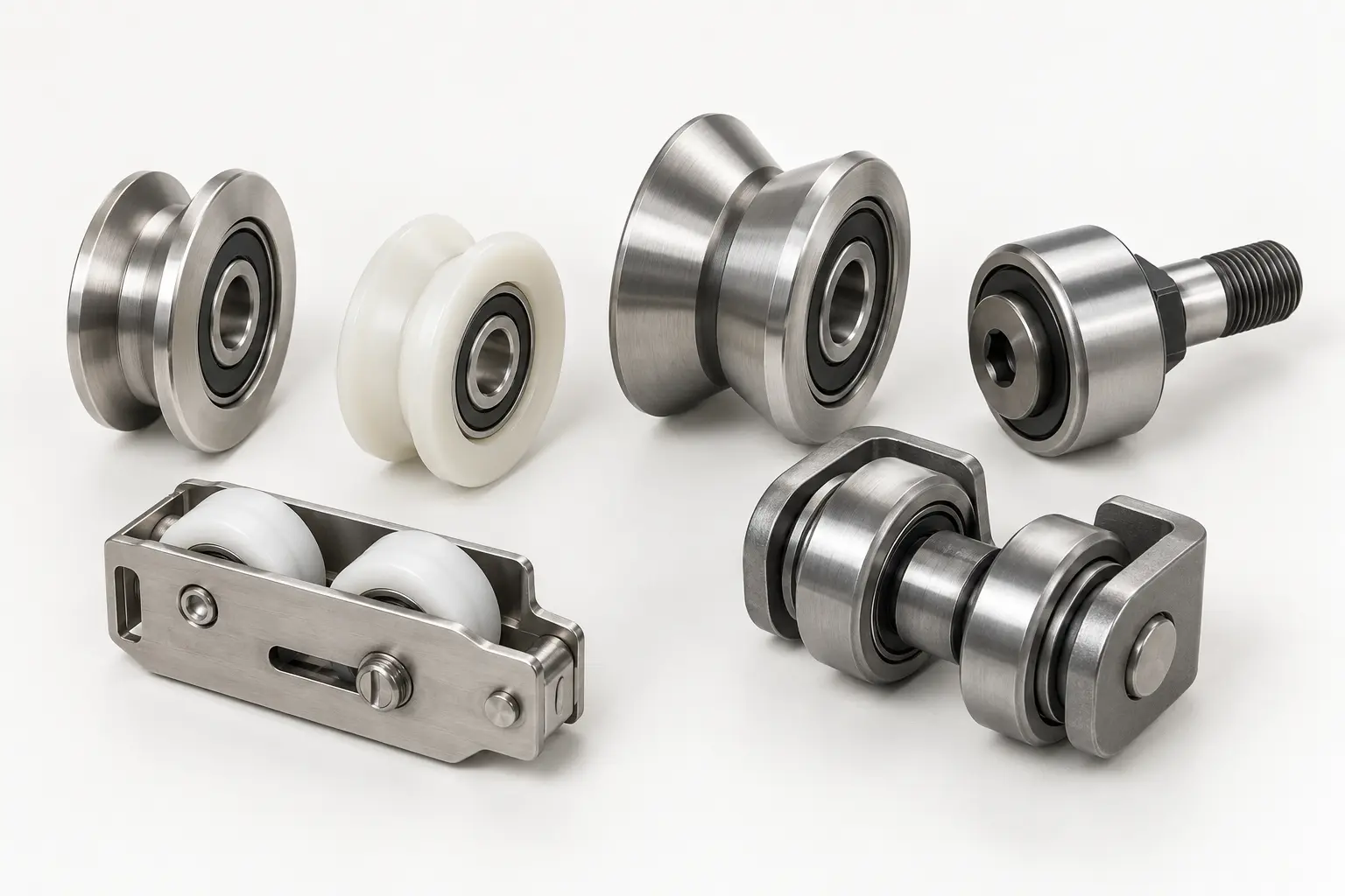
A used roller is evidence, not automatically the master dimension. A flat worn onto the rolling surface can reduce diameter. A polished groove can become wider or deeper. A bent bracket can move the wheel centreline, while a loose bore may indicate damage rather than the original fit.
Compare multiple unused or less-worn samples when available. Measure the mating shaft, bracket and track, then mark uncertain dimensions on the draft drawing. The buyer should approve the reconstructed geometry before tooling or batch production.
Application Data the Drawing Cannot Show
- Door or sash weight and number of load-carrying rollers
- Sliding direction, adjustment range and expected cycle frequency
- Indoor/outdoor use, dust, rain, salt or cleaning chemicals
- Noise target and acceptable running resistance
- Temperature range and storage conditions
- Known failure mode: seizure, noise, wear, corrosion, cracking or derailment
- Target market, trial quantity and annual demand
These details help distinguish a dimensional copy from an application-matched replacement. Claims such as “heavy duty” or “weatherproof” should be converted into an agreed operating condition or test.
From Draft Drawing to Approved Sample
- Identification: classify the item as bare bearing, finished wheel or complete assembly.
- Draft measurement: record visible geometry and flag worn or inaccessible areas.
- Mating-part check: compare shaft, housing, bracket and track dimensions.
- Manufacturing review: agree materials, closures, tolerances, tooling and feasible quantity.
- Prototype: test installation, movement, adjustment, load and noise in the real system.
- Drawing approval: freeze the revision and any accepted deviation.
- Repeat-order control: retain sample, inspection points, label and packing references.
A prototype should be tested across the adjustment range, not only at one position. Check that the wheel remains aligned, clears the bracket and contacts the intended track surface.
Inspection Points for Incoming and Pre-Shipment Checks
| Check | Evidence |
|---|---|
| Critical dimensions | Measured results against the approved drawing |
| Bearing identity | Model/closure, appearance and approved source reference |
| Rotation and noise | Agreed manual or instrumented method |
| Profile and concentricity | Gauge, drawing comparison or specified runout method |
| Assembly fit | Approved fixture, bracket, rail or retained master sample |
| Identification and packing | Label, inner pack, carton quantity and lot reference |
When to Choose Each Product Route
- Choose non-standard door and window bearings when the core bearing or ring geometry is the main custom item.
- Choose the custom bearing category when you need to compare door/window, miniature-size and machinery routes.
- Choose the existing plastic bearing roller wheel when the complete POM, nylon or coated wheel is required.
- Choose custom machinery bearings when the same sample-to-drawing method is used outside architectural hardware.
Frequently Asked Questions
Can a replacement be quoted from photos only?
Photos can identify the product family, but a reliable quotation normally needs measured dimensions, the application and preferably a drawing or physical sample.
Should a worn roller be copied exactly?
No. Wear can change the diameter, groove and fit. Compare the sample with mating parts and agree reconstructed dimensions on the drawing.
What creates a repeatable reorder?
An approved drawing revision, retained sample, inspection method, bearing reference, label and packaging specification create a stable reorder standard.
Convert Your Sample into a Quotation Package
Send front/side/installed photos, d × D × B dimensions, finished roller profile, bracket or track data, operating conditions, trial quantity and annual demand.